The Turboelectric Team
Krinal Doma, Miranda Daane, Michael Kusz, Karina Hollis-Brau, Yash Pande
Project Objective
Design, Build and Test a hybrid Turbo electric engine that integrates internal combustion and electric power to enhance fuel efficiency, emissions and overall system efficiency
Outline
- System Requirements and Design Overview
- Test Objectives
- Data & Control System
- Instrumentation Diagram
- Hoffman Box Measurements
- Abort Conditions and Safety Considerations
- Implementation Challenges
- Final Results
- Project Reflection
Updated System Requirements
Top Level Requirements
| Top Level Requirements | |
|---|---|
| TLR-100 | System shall adhere to laboratory policies, ensuring safety and consistency in operation |
| TLR-200 | System will provide thrust through an electric ducted fan configuration |
| TLR-300 | Data will be recorded for essential power information: Amperage, Generator RPM, Voltage, Thrust, and Efficiency |
| TLR-400 | System design size shall not exceed a volume of 1.5 x 1.5 x 2 ft. |
| TLR-500 | Lead times for components should indicate arrival by Week 8 |
| TLR-600 | Project cost shall not exceed $3000 |
| TLR-700 | Voltage and power should adhere to each and every downstream component |
| TLR-800 | System shall have a minimum efficiency of 20% |
| TLR-900 | Total weight of system shall not exceed 20 kg |
| TLR-1000 | Thrust should be generated by the system using a combination of chemical and electrical energy |
| TLR-1100 | System should be able to withstand mechanical vibrations from 20 to 2000 Hz in all three axial directions |
Design Overview
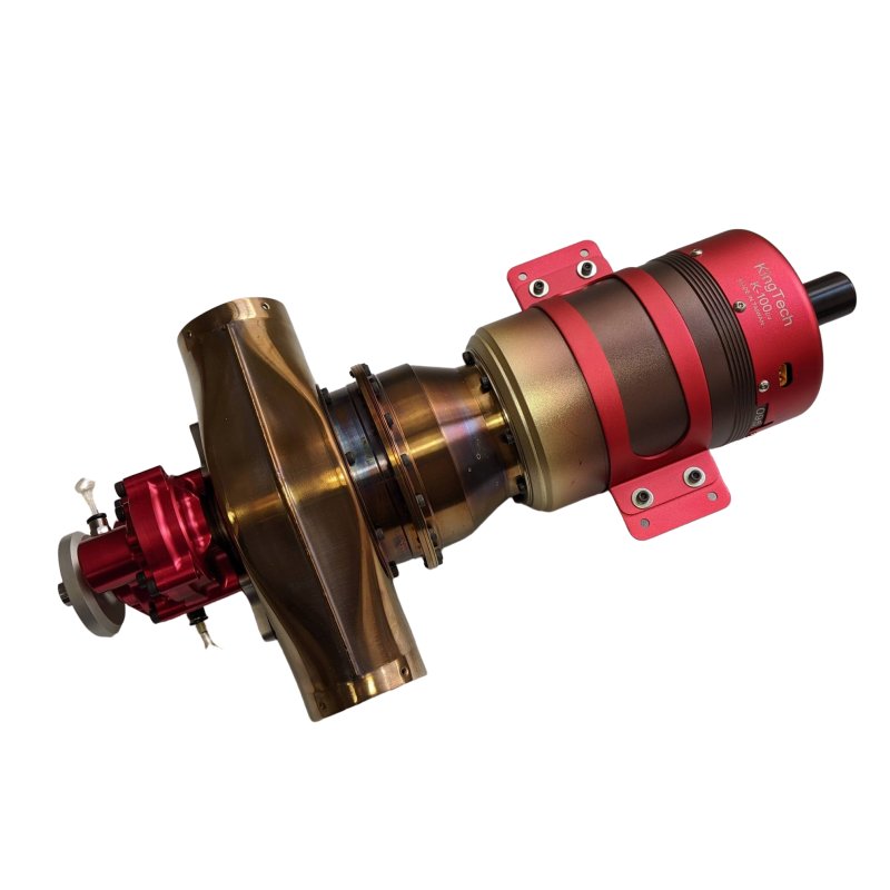
- KingTech K-100TPG4+ Turboshaft Engine
- Generator Subsystem:
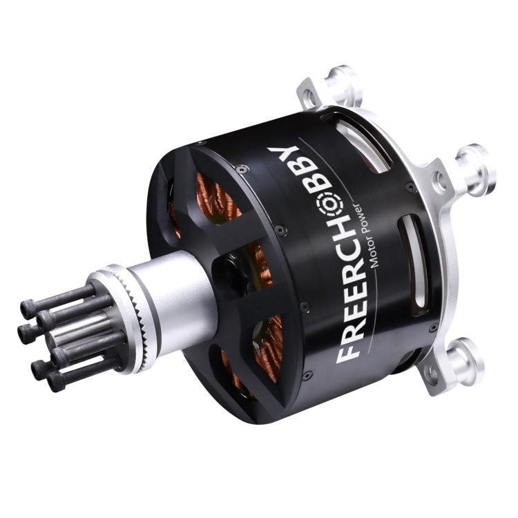
- Free RC Hobby Motor (Generator)
- Rectifier
- Capacitor
- Relay
- Free RC Hobby Motor (Generator)
- Battery Subsystem:
- LiPo Batteries
- Fuses & Contactors
- Propulsive Subsystem:
- Electric Speed Controllers (ESCs)
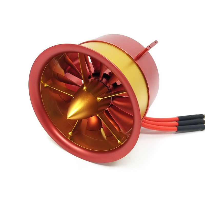
- Electric Ducted Fans (EDFs)
Data & Control System
Zucrow PXIe DAQ
- DAQ Channeling
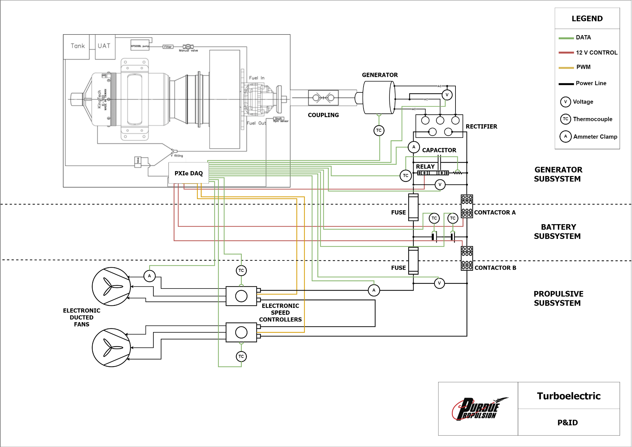
- Assign 12 Input Lines (Analog Signals from System 12V)
- 3 Voltmeters (Battery and EDF Safety)
- 4 Thermocouples (Generator, Battery and Capacitor Safety)
- 2 Ammeter (For efficiency)
- 3 12V Output Control Lines
- Relay for Capacitor Discharge
- Subsystem Control
- 3 PWM Output (Generated from DAQ )
- ESC Throttle
- Engine Throttle
- Assign 12 Input Lines (Analog Signals from System 12V)
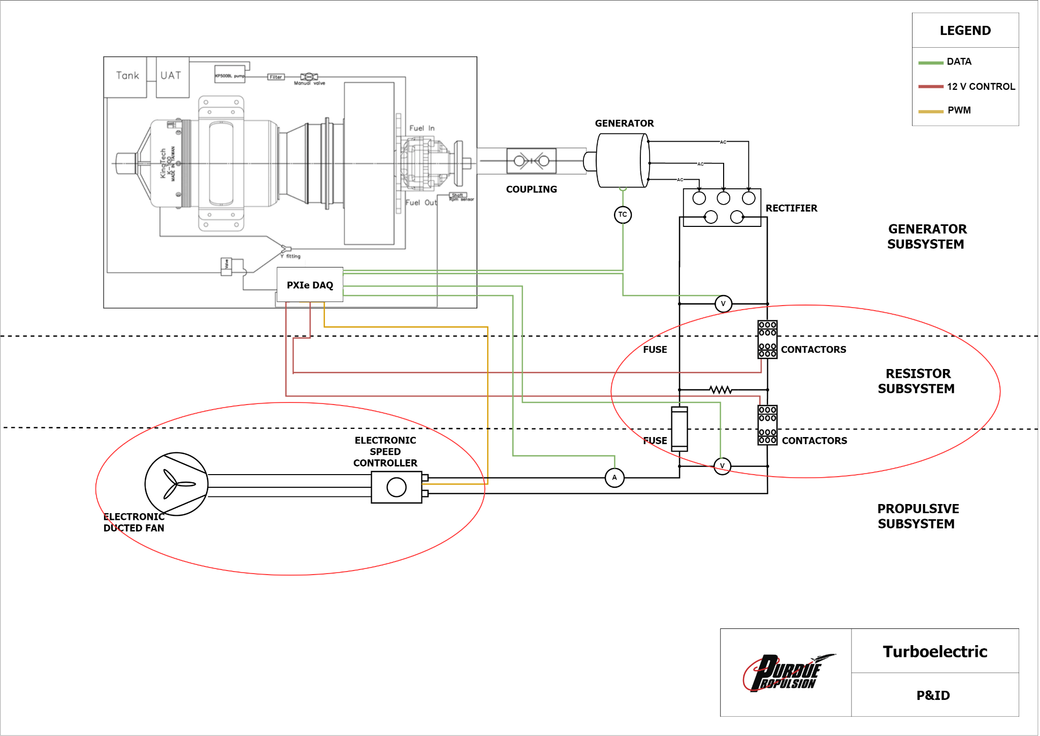
Instrumentation Diagram (P&ID)
Test Objectives
- Evaluate Performance of Turboelectric Engine
- Thrust vs. Time curve
- Overall Power Required for EDFs
- Measure Total Run Time of EDFs using Battery Power
- Battery power storage capabilities
- Monitor Voltage, Current, and Temperature throughout the system vs RPM
- Determine Efficiency of Electronic System
- Measure Thrust Power Output and Shaft Power Input to system for overall efficiency
- Calculate Component Efficiency (electrical losses)
Hoffman Box
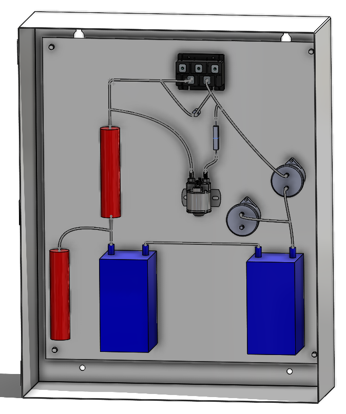
| Hoffman Box Components and Dimensions | |
|---|---|
| Rectifier | 3.74” x 2.83” x 1.37” |
| Battery (x2) | 7.48” x 3.89” x 4.37” |
| Circuit Breakers (x2) | Dia: 2.6”, Lg: 2.87” (approx.) |
| Capacitor | Dia: 0.52”, Lg: 0.78” (approx.) |
| Fuse (x2) | Dia: 1.5625”, Lg: 7.125” |
| Overall Box | 30” x 24” x 8.125” |
Abort Conditions
- Measured Current exceeds 200 A (Electrical System Shortage)
- Battery temperature warning at 80 °C, abort at 100 °C
- LiPo Battery Ignition occurs at 140-160 °C, fire suppression bag will mitigate effects of fire
- Thermocouple temperature reading reaches 100 °C on all other components
- Voltage exceeds 100 V
- Loss of electrical signal
- Fire of any sort
- Electrical fire, Turboshaft engine fire
- Turboshaft Engine abort conditions
- Shaft Overspeed
- Engine temperature exceeding limit
Safety Considerations
- LiPo Battery Safe Bag (Fire Proof)
- Electrical discharge of hazardous components
- Guarantee capacitor does not hold dangerous levels of charge when the system is not operating
- Discharge through Relay + Resistor
- Ensure system is de-energized when not in operation
- Guarantee capacitor does not hold dangerous levels of charge when the system is not operating
- Safeguarding exposed electrical circuitry
- Hoffman box
- Continuous monitoring of Current, Voltage, and Temperature levels throughout the system
- Engage circuit breakers should levels rise above the safety threshold
- Fuses will trigger any spike in currents
Implementation Challenges
- Sizing the Capacitor


- For a tolerance of 10 V, we need a one milli-F Capacitor.
Battery Safety
- After running the Generator subtest, Voltage was too unpredictable to maintain within a reasonable threshold
Updated Instrumentation Diagram (P&ID)
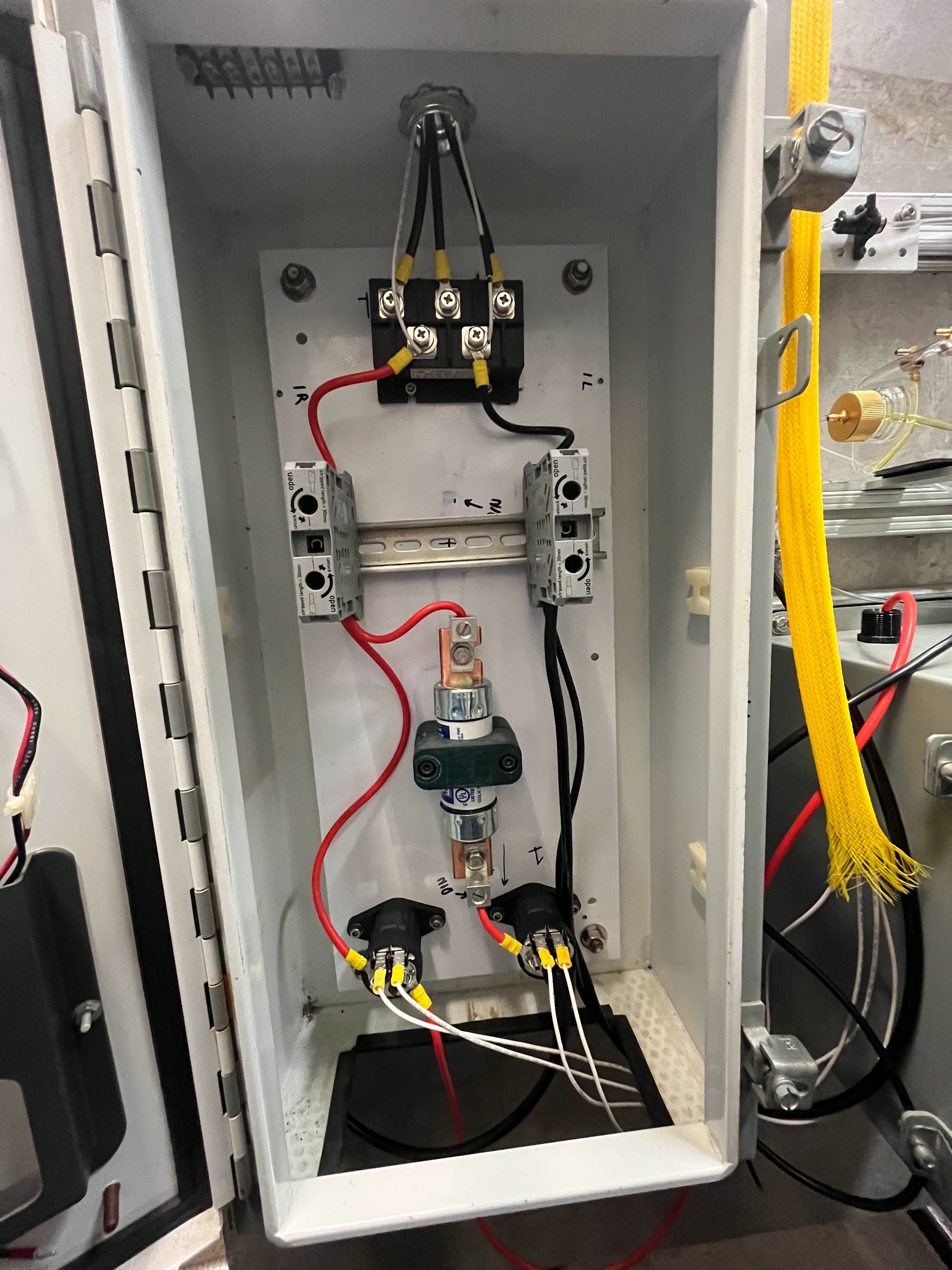
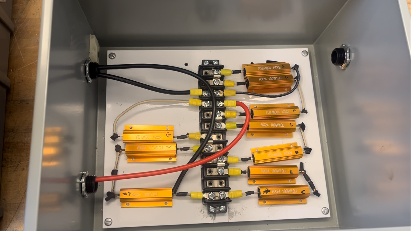
Assembly
The Resistor Box has a net Resistance of 10 Ohms
Max Current 6A
Test Video
A Success

Final Results
The test rig was able to successfully transmit at least 3.4 kW of power from the engine to the fan.
System Efficiency larger than 26%
Approximate Net Thrust between 62-64N
| Engine status | ESC status | Turbine RPM | Generator RPM | Voltage | Current |
|---|---|---|---|---|---|
| Idle | Disconnected | 45,000 | 1470 | 29.4V | 4.3A |
| > Idle | Connected | ~80,000 | 1250 | 24.97V | 40A |
| > Idle | Connected | 100,000 | 1789 | 35.78 V | 95A |
Total budget expense: ~$3,150
| Turbo electric Module | Part Number | Supplier | Count | Unit Price | Cost |
|---|---|---|---|---|---|
| Motor or Generator | MP 12090 | Free RC Hobby | 1 | $388.00 | $388.00 |
| Electric Ducted Fans | JPH-EDF-120-12S-CCW | JP Hobby | 2 | $499.00 | $1040.72 |
| LiPo Batteries | LiPo 6000 12S | Amazon | 2 | $450.00 | $1,140.72 |
| Electronic Speed Controller | NA | Amazon | 1 | $149.99 | $149.99 |
| Battery Safe Bags | NA | Amazon | 1 | $13.99 | $13.99 |
| 80-20 T-Slotted Aluminum Rail | 470ST0511 | McMaster | 1 | $243.57 | $243.57 |
| WAGO Terminal Blocks | 2948-265 150-ND | DigiKey | 5 | $20.40 | $102.00 |
| Contactors | 576-DRC110012 | Mouser Electronics | 3 | $52.21 | $156.63 |
| Total | $3,150.45 |
System Success
Top Level Requirements
| Top Level Requirements | |
|---|---|
| TLR-100 | System shall adhere to laboratory policies, ensuring safety and consistency in operation |
| TLR-200 | System will provide thrust through an electric ducted fan configuration |
| TLR-300 | Data will be recorded for essential power information: Amperage, Generator RPM, Voltage, Thrust, and Efficiency |
| TLR-400 | System design size shall not exceed a volume of 1.5 x 1.5 x 2 ft. |
| TLR-500 | Lead times for components should indicate arrival by Week 8 |
| TLR-600 | Project cost shall not exceed $3000 |
| TLR-700 | Voltage and power should adhere to every downstream component |
| TLR-800 | System shall have a minimum efficiency of 20% |
| TLR-900 | Total weight of system shall not exceed 20 kg |
| TLR-1000 | Thrust should be generated by the system using a combination of chemical and electrical energy |
| TLR-1100 | System should be able to withstand mechanical vibrations from 20 to 2000 Hz in all three axial directions |
Project Reflection
- Design Recommendations
- Sizing of Capacitor as early as possible with simulations
- Alternative Safety to Fuse
- DAQ Integration for PWM Control
- Management Recommendations
- Weekly Deliverables
- Early Subsystem Testing
- Electrical Engineers as advisors
- Have an Online Schematic for Design Changes to be Cleared
Conclusion and Recommendations for the Future
In conclusion, the basic design of the electric generator mounted to a turboshaft, which then runs electrical power to one ESC and EDF to generate thrust, ran smoothly without much issue. This gives a baseline for a more complicated design, factoring in batteries for energy storage, more EDFs for greater thrust, and a more significant focus on strengthening system efficiency. The following steps would include developing a more developed control system for the turboelectric engine. The current setup only allows control over turboshaft throttling. For future testing, a PID controller can be designed to send throttle commands by indicating a desired RPM for the EDF, which then communicates with the turboshaft a specific throttle level based on the power level demanded by the indicated fan output RPM. A more developed control system would also allow further analysis of the turboelectric motor's electronic side to understand system efficiency better. The team would also highly recommend a better way to measure thrust from the EDF and a way to measure turboshaft engine power output. These values can help calculate efficiencies. Another improvement to the system that should be explored further would be using a capacitor to smooth ripple voltage output by the rectifier. However, safety considerations for this component must be heavily examined due to the risks discharging a capacitor presents. Future steps also include investigating the use of a LiPO battery within the system. The team encountered numerous issues integrating the batteries, primarily due to safety concerns when charging them with the turboshaft. If a battery is included in the system, it would be wise to include a controller that shuts off power when the circuit's current exceeds the safe charging limit. More research into using LiPo batteries is needed to understand the best practices for using them in such a system further. Finding and consulting experts in this field is recommended to move forward. The original design for the system consisted of two batteries and two EDFs. The team decided to move forward with no batteries and a single EDF for testing, both for simplicity and since an ESC with a higher current rating was needed. Purchasing an additional ESC with a higher current rating (recommended 150A) for use in a system with two fans is another future direction this project can take. Additionally, preliminary tests utilized a manual switch to control the contactors. Originally, the contactors were to be activated using the DAQ system on the computer, but due to the insufficient voltage ratings, a manual switch was constructed. Locating proper contactors (24V) to integrate the system into the existing DAQ would make testing easier and aid in the design of a more developed control system.