The Team
Ignacio Lasala Aza, Ethan Hund, Chase Jenquin, Krinal Doma, Lance Coomar,Stephanie Farney,Alexander Hodge
Introduction and Overview
Hypersonic weapons concepts have seen a significant growth in interest and subsequent research due to advances in the weapons capabilities of our adversaries. Consequently, the Department of Defense has come to consider hypersonic capabilities as paramount to the safety of the nation and as a result, has invested heavily in the development of these vehicles. To date, scramjets, or supersonic combustion ramjets, are the best candidates for maneuverable, hypersonic weapons due to their high specific impulse in these flight regimes [@scramjets]. In theory, scramjets offer noteworthy advantages over conventional strike weapons, such as design simplicity and greater potential for maneuverability due to their use of aerodynamic lift. Additionally, their speed and relatively low cruise altitude make them more challenging to detect promptly, significantly reducing the time adversaries have to deploy countermeasures.
While these systems have great potential, scramjets pose multiple significant design challenges. The high flight speed creates large thermal loads, driving both cooling systems and material selection. In addition, vehicle performance degrades as Mach number increases [@thermal]. Specific to the propulsion system, the inlet is highly sensitive to changes in flight condition. For a fixed geometry system, significant deviation from the design point can result in inlet unstart, combustor flame-out, and potentially vehicle loss if relight cannot be achieved. Efficient operation beyond the design point therefore necessitates the need for variable geometry, which adds a layer of complexity to the system and reduces reliability as a result, or rectangular-to-elliptical shape transition inlets, which involve complex geometry that may not be practical from a manufacturability standpoint [@RESTinlet]. Additionally, sustaining combustion at supersonic speeds has proven notoriously difficult due to flow behaviour within the combustor. At supersonic speeds, combustion of fuel results in significant pressure rise and subsequent boundary layer separation, which can propagate upstream and result in inlet unstart. This necessitates the need for an isolator [@isolator].
This report details the design and analysis of a scramjet-propelled vehicle and assesses its performance against the following criteria:
-
Range: > 500 miles
-
Initial weight: < 4000 lb
-
Must be launched from a B-52
-
Must be manufactured from existing materials
-
Must use hydrogen as fuel
In order to evaluate performance, the overall geometry of the system and its components has been defined as well as the trajectory, engine cycle, and thermal protection system. Figure shows a representative Computer-Aided Design (CAD) render of the vehicle. Subsequent sections will give more detail regarding each component of the vehicle design.

Trajectory and Performance
Trajectory analysis results often inform vehicle design. The enclosed scramjet design leveraged Optimal Trajectories by Implicit Simulation (OTIS). OTIS is a 6 degrees of freedom (6DOF) NASA trajectory optimization code that can be used for parametric design and maximizing performance. This code can be used throughout the design process to assess range performance and inform various aspects of the design: desired thrust level, necessary fuel weight, and booster sizing. The OTIS model for this application is structured in 5 phases:
-
Drop from the B-52
-
Constant thrust boost
-
Separation of flight vehicle from booster
-
Powered cruise
-
Power-off glide
Figure [2] a includes an overview of the trajectory profile with labels for each phase.
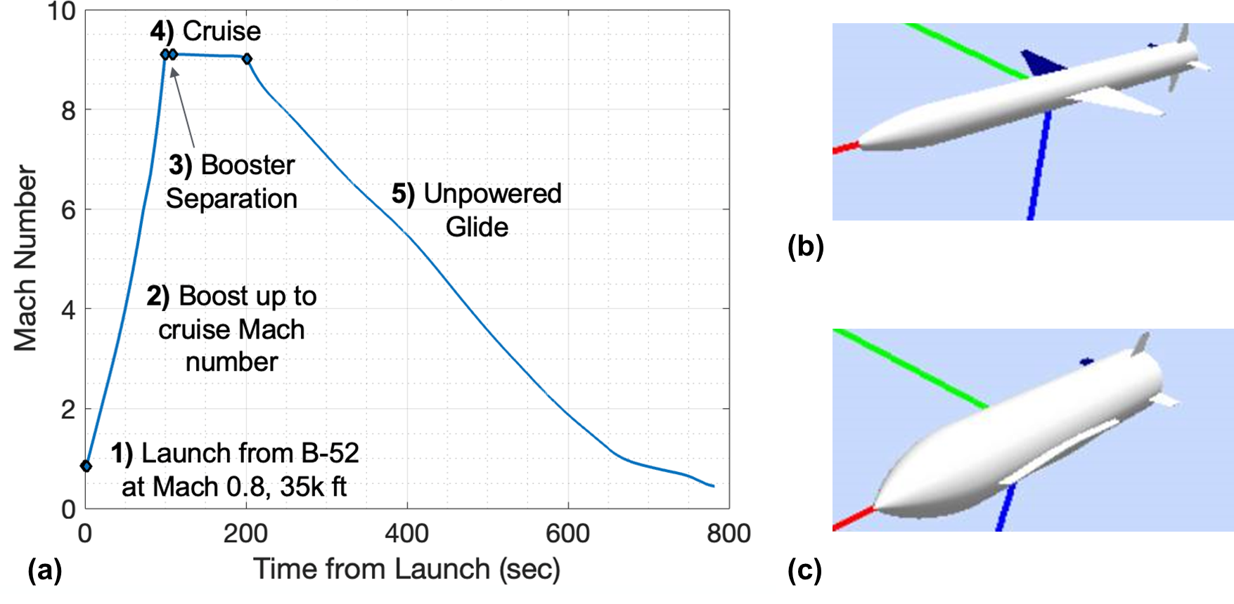
The evaluation of external aerodynamics performance was conducted using the Missile Data Compendium, commonly referred to as Missile DATCOM. This semi-empirical tool for predicting aerodynamics merges historical missile design data with theoretical insights, offering accurate preliminary geometry assessments. The historical data foundation of Missile DATCOM means it excels with geometries similar to those in its existing database. To align with this, the flight vehicle was represented as an axisymmetric shape with an equivalent frontal area to the actual vehicle design, ensuring a close approximation of drag. To compensate for potential lift discrepancies, low aspect ratio wings, or strakes, were integrated along the vehicle's body.
For visual reference, the geometries applied in Missile DATCOM for the booster and the flight vehicle are depicted in Figures 2a and 2b, as seen in the linked references. The booster's design was inspired by the Pegasus booster, detailed in Lindberg's work, and assumed to have a specific impulse of 300 seconds.
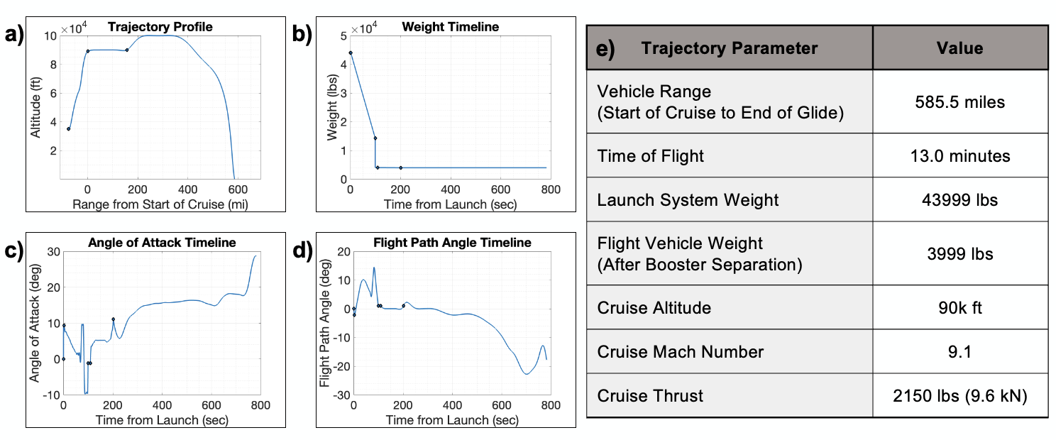
OTIS operates as an optimization tool, selecting the optimal parameters at each step to enhance the objective function. Figure 3 illustrates OTIS's strategic adjustments to meet the predefined flight profile constraints. Notably, during the cruise phase, the flight path angle is maintained at a maximum of 2 degrees, as demonstrated in Figure 3d. A significant negative angle of attack is employed post-boost to swiftly stabilize the missile for the scramjet flight segment, depicted in Figure 3c. Figure 3e provides a summary of the key trajectory performance parameters.
Cycle Analysis
To begin the propulsion system design, it was required to know the optimum design points, namely the ideal cruise Mach number , total temperature at the exit of the combustor , and altitude . First, an ideal cycle analysis was conducted to gain rough estimates of these operating conditions both to facilitate aerothermal component system designs and to enable quick calculations of broad ranges of operating conditions. This ideal cycle analysis was based on the standard ideal Brayton cycle and assumed perfect efficiency for all of the propulsion subsystems.
Figure 4 (a) gives a representative plot of specific fuel consumption (SFC) vs specific thrust at Mach and shows, in an ideal case, how the SFC decreases with decreasing and increasing specific thrust and how the specific thrust tends to increase with increasing . To pick a design point, the at which a minimum SFC is produced for a certain altitude and Mach number was used. In the particular case (Mach ) shown in Figure 4 (a) the lowest SFC corresponded to a considerably high at an of ft and a of K which, after comparing with the other Mach number cases studied, gave the chosen design point for the ideal cycle analysis.
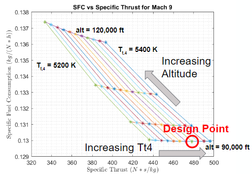
Figure 4 (a) Ideal cycle analysis performance trends
.
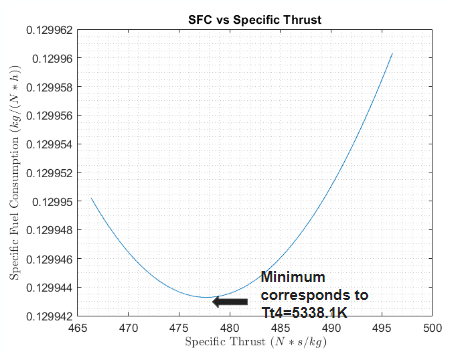
Figure 4 (b) Semi-ideal cycle analysis optimization of specific fuel consumption.
Using the initial values chosen from the ideal cycle analysis, a semi-ideal cycle analysis based on the work by Choi (Choi 2014) was conducted to further refine the design conditions. Some assumptions often used in ideal cycle analyses are relaxed; while not every aspect is perfectly realistic. For example, the mass flow rate into the nozzle is not assumed to be the same as the flow rate leaving the nozzle due to the addition of fuel (), but the nozzle is assumed to be perfectly expanded (). Additionally, Choi (Choi 2014) uses a semi-ideal formulation that solves for the optimum when the combustion Mach number is less than which was included in the procedure.
After iterating through varying design points with this semi-ideal analysis, Mach and ft were found to be ideal, and Figure Figure 4(b) shows a representative plot of SFC vs at these conditions, demonstrating that the minimum SFC corresponds to a of K.
Aerothermal Analysis and Design
Using the chosen design point from the cycle analysis, a one-dimensional aero-thermodynamic model was formulated to choose the design parameters of the scramjet engine. The major components included in the analysis are the inlet, isolator, combustor, and nozzle. Separate methodologies were implemented for each component, and a combined code was developed to calculate performance metrics of the entire engine, along with the non-dimensional length of the engine, which was scaled by the inlet capture area. Crucial outputs include component efficiencies and , which was used to determine the required air mass flow rate and resulting vehicle size based on the thrust requirement from the trajectory analysis. Subsequent sections focus on the design approach for each subsystem of this analysis.
Inlet Design
Inlet Design Methodology
To determine the geometry of the inlet, Latin Hypercube sampling (similar to Monte Carlo methods) was used to generate a large number of semi-random combinations of ramp angles for a 2-D fixed geometry inlet with between two and four compression ramps. The final ramp angle was set so that the flow exiting the inlet is parallel to the freestream and all ramp angles were rounded to the nearest in order to support manufacturability. Once these parameters were set, the shock angles, static and total pressure ratios, static temperature ratio, and Mach numbers were determined using theta-beta-M relations. A three-dimensional plot of the entire design database showing the relationship between the static pressure ratio , the total pressure ratio , the exit Mach number , and the overall number of compression ramps is plotted in Figure 5 (a). To identify the best design, the database was filtered for solutions that meet the criteria developed in the overall cycle analysis. These minimum criteria are summarized in the table on Figure 5 (b).
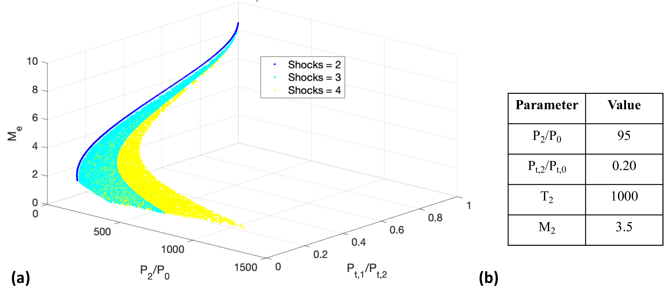
Figure 5 (a) Scatter plot of the inlet design space with varying exit Mach number , total pressure ratio , and static pressure ratio . (b) Table of bounding parameters used to refine the inlet design.
Additionally, designs that experienced separation were excluded from the filtered design space. For each design, between each shock, this was evaluated against the Korkegi limit (Smart 2007), which is defined in Korkegi equation:
Finally, after filtering for all of the above criteria, the final design was determined by selecting the inlet with the shortest length-to-height ratio in order to reduce vehicle size and drag. The final design geometry was kept nondimensional so that it could be scaled to achieve the target mass flow. The performance of the inlet is summarized in Table (2) and the geometry is shown in Figure 6 (a). The chosen design was checked against the isentropic and Kantrowitz limits to ensure it would be started at the cruise point. These limits, as well as where the selected inlet is located with respect to those limits, are shown in Figure 6 (b). Note that for external and mixed compression inlets, the limits are assessed based on the geometry and Mach number at the cowl enclosure, as described by Flock and G"ulhan

Figure 6 (a) Nondimensional geometry of the inlet, and expected oblique shock locations. (b) Final Inlet With Respect to Kantrowitz and Isentopic Limits.
Isolator and Combustor Design Methodology
Isolator design involved a control volume analysis with a growing boundary layer that defines the core flow at the exit, which is assumed to contain all mass flux out of the isolator. Mass and momentum conservation equations were solved to yield a nonlinear system of equations, which was solved with numerically with a prescribed static pressure ratio . The length of the isolator was calculated using the Waltrup and Billig empirical correlation for shocks in a cylindrical duct, where the duct diameter was assumed to be the height of the isolator (Waltrup 1973). was iterated on to provide an adequate combustor inlet Mach number while maintaining a reasonable isolator length and total pressure loss.
To estimate combustor performance, a supersonic mixing model was implemented, which uses a prescribed mixing efficiency profile and calculated mixing length to define an effective equivalence ratio profile along the combustor (Birzer, 2009). is calculated using equation below, which defines the length at which all of the injected fuel is available for combustion. Compressible turbulent mixing layer growth is corrected for with the compressibility factor , which is a function of the convective Mach number (Papamoschou, 1988). is defined in equation below, along with the empirically defined constant from experiments in a hydrogen scramjet with strut injection (Gerlinger, 2000).

Figure 7 (a) Geometry of the 2-strut injector by Chaubey et al. (b) Plot of injector H mass fraction and (c) injector velocity streamline profiles at a combustor inlet Mach number of 2.5 (Choubey).
Strut injection was chosen due to the benefit of increased fuel penetration, which is a concern in scramjet combustors due to hydrogen's low density (Tian). Specifically, a 2-strut injector design was chosen from Chaubey et al. (Choubey). Figure 7(a) illustrates the injector geometry and shape, which features a pair of symmetric, diverging ramp struts. Fuel is injected from the aft end's semi-circular trailing edge with at an angle of 40 degrees. Computation fluid dynamics simulation (CFD) results of this design indicate superior mixing efficiency compared to a single strut injectors at of 2.5. Figure 7(b) shows the hydrogen mass fraction profile of the injector, which highlights the rapid growth of the mixing layer thickness as shear layer instabilities convect along the combustor. Velocity contour plots from fuel injection are shown in Figure 7(c), which highlights the existence of large recirculation zones that further enhance mixing and flame holding.
Injection of the fuel occurs at the start of the combustor, as illustrated in Figure 8(a). Stations 2 and 3 denote the inlet and exit of the isolator, is the length of the combustor, and the blue shapes illustrate approximate location of the injectors. The mixing efficiency profile from Chaubey et al. is plotted along with the calculated mixing efficiency used in this work in Figure 8(b). Adequate agreement between the curves is observed, and suggests that the chosen injector can perform at or better than the theoretical mixing performance employed in this work.

Figure 8 (a) Illustration of injection location with station locations labeled. (b) Experimental and model mixing efficiency profiles normalized by mixing length (Choubey)
The combustor design was formulated using the described mixing model and injector design. Frictionless flow was assumed, and because of the small fuel air ratios necessary for hydrogen, mass addition from fuel injection was neglected. The axial variation of Mach number was calculated by numerically solving a 1-D ordinary differential equation (ODE) derived from the Shapiro compressible flow equations (Shapiro). This equation assumed a shock free isolator, with both an area profile and total temperature profile as prescribed inputs. The combustor was discretized axially, and a diverging duct geometry with an expansion angle provided the area profile. An energy balance was performed at each discretized step using Cantera, which calculated the change in equilibrated combustion gas mixture properties and enthalpy given the effective at each step as calculated from the mixing efficiency. The resulting total temperature profile and area schedule was fed into the solver, after which the remaining flow properties could be calculated and used to update the specific heat of the mixture at each step.
Of the major combustor parameters, higher , lower , and higher were desired for improving mixing efficiency and subsequently increasing temperature rise, which supported higher engine thrust. This effect was competed by the limit of flow separation, which was assumed to occur if the Mach number at the point of higher combustor static pressure was less than of the combustor inlet Mach number (Heiser). Additionally, a maximum static temperature limit of 3400 K was imposed from initial estimates of the thermal analysis in order to ensure material survivability. A combustor length of was chosen to maximize mixing efficiency, and was chosen to maximize within the stated limits. was then adjusted to give adequate margin in avoiding flow separation and thermal choking.